Appearance
分布式存储前端 RDMA/TCP 融合组网配置
《H3C RoCE 网络开局一本通》拆分章节,文档版本:6W102。
3.5.1 组网需求
如图所示:
分布式存储场景前端网络 RDMA 网络采用 Spine、 Leaf 两级架构, Spine 设备为 S9825-64D, Leaf 设备为 S9855-24B8D。
Leaf 设备作为服务器的网关, Spine、 Leaf 之间为三层 ECMP 网络,每组 Leaf 采用不同网段的网关,通过 OSPF 或者 BGP 发布网段路由在进行数据高速转发的同时支持转发路径的冗余备份。
同一组 Leaf 设备的成员设备之间运行 M-LAG (Multichassis Link Aggregation,跨设备链路聚合),双活设备之间使用 200G 端口互联,为了保证可靠性横穿链路至少 2*200G, Peer-link 上不配置 PFC。
Leaf 配置双活网关,双活网关配置相同的 IP 和 MAC。
计算节点服务器网卡采用 bond4 工作模式(动态聚合模式),存储节点服务器网卡采用多 IP 非 bond 模式。
现要求实现 RDMA 应用报文使用队列 5 进行无损传输。
本文以 2 台 Spine 设备、 8 台 Leaf 设备示例。实际应用中 Spine 层部署 2 台 S9825-64D 设备、 Leaf 层部署 16 台 S9855-24B8D 设备(上行口使用 8400G,下行口使用 16200G)可以实现收敛比 1: 1 的 RDMA 网络。
服务器网卡使用 bond4 工作模式时,其接入交换机需要配置动态聚合。
图 3-6 数据中心分布式存储场景前端网络 RDMA/TCP 融合组网图
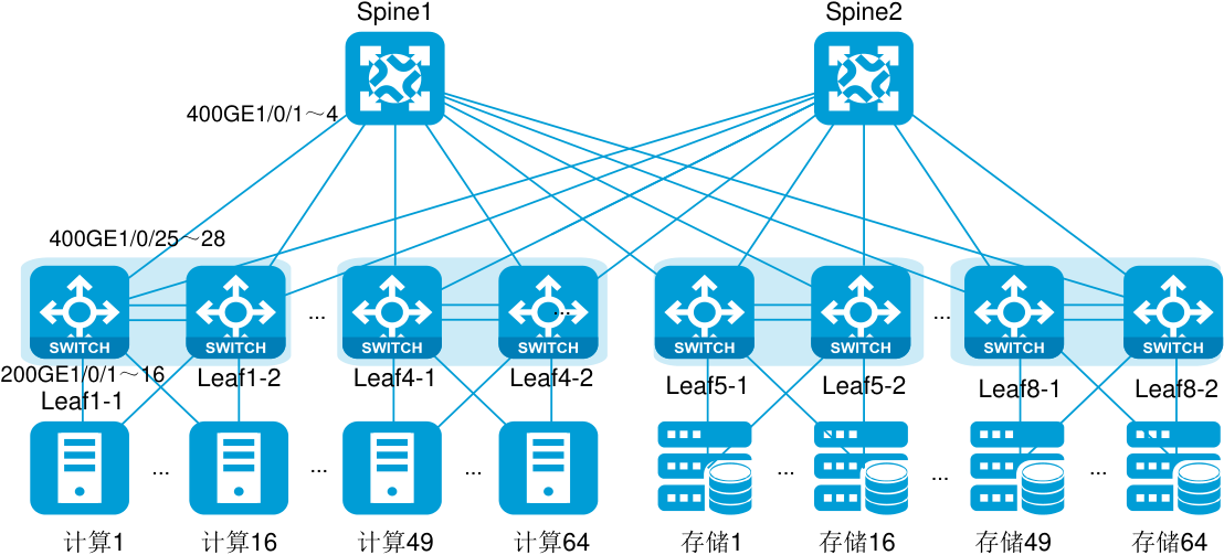
表 3-7 接口和 IP 地址规划
| 设备 | 接口 | IP地址 | 设备 | 接口 | IP地址 |
|---|---|---|---|---|---|
| 200GE1/0/1~16 | Vlan 100 | 400GE1/0/1 | 9.179.56.0/31 | ||
| 400GE1/0/25 | 9.179.56.1/31 | … | … | ||
| … | … | 400GE1/0/8 | 9.179.56.14/31 | ||
| 400GE1/0/28 | 9.179.56.7/31 | 400GE1/0/57 | 9.179.56.112/31 | ||
| Lf11 | 400GE1/0/29 | 9.179.56.129/31 | Si 1 | … | … |
| ea- | … | … | pne | 400GE1/0/64 | 9.179.56.126/31 |
| 400GE1/0/32 | 9.179.56.135/31 | ||||
| 200GE1/0/17~18 | KeepAlive成员口 | ||||
| 200GE1/0/19~20 | Peer-Link成员口 | ||||
| Vlan-int100 | 9.179.64.1/26 | ||||
| 200GE1/0/1~16 | Vlan 100 | 400GE1/0/1 | 9.179.56.128/31 | ||
| 400GE1/0/25 | 9.179.56.9/31 | … | … | ||
| … | … | 400GE1/0/8 | 9.179.56.142/31 | ||
| Leaf1-2 | 400GE1/0/28 | 9.179.56.15/31 | Spine 2 | 400GE1/0/57 | 9.179.56.240/31 |
| 400GE1/0/29 | 9.179.56.137/31 | … | … | ||
| … | … | 400GE1/0/64 | 9.179.56.254/31 | ||
| 400GE1/0/32 | 9.179.56.143/31 | ||||
| 200GE1/0/17~18 | KeepAlive成员口 |
| 设备 | 接口 | IP地址 | 设备 | 接口 | IP地址 |
|---|---|---|---|---|---|
| 200GE1/0/19~20 | Peer-Link成员口 | ||||
| Vlan-int100 | 9.179.64.1/26 | ||||
| 200GE1/0/1~16 | Vlan 100 | ||||
| 400GE1/0/25 | 9.179.56.113/31 | ||||
| … | … | ||||
| 400GE1/0/28 | 9.179.56.119/31 | ||||
| Leaf 8-1 | 400GE1/0/29 | 9.179.56.241/31 | |||
| … | … | ||||
| 400GE1/0/32 | 9.179.56.247/31 | ||||
| 200GE1/0/17~18 | KeepAlive成员口 | ||||
| 200GE1/0/19~20 | Peer-Link成员口 | ||||
| Vlan-int100 | 9.179.65.193/26 | ||||
| 200GE1/0/1~16 | Vlan 100 | ||||
| 400GE1/0/25 | 9.179.56.121/31 | ||||
| … | … | ||||
| 400GE1/0/28 | 9.179.56.127/31 | ||||
| Leaf 8-2 | 400GE1/0/29 | 9.179.56.249/31 | |||
| … | … | ||||
| 400GE1/0/32 | 9.179.56.255/31 | ||||
| 200GE1/0/17~18 | KeepAlive成员口 | ||||
| 200GE1/0/19~20 | Peer-Link成员口 | ||||
| Vlan-int100 | 9.179.65.193/26 |
Spine2 端口编号规则与 Spine1 一样; Leaf1-2/8-1/8-2 端口编号规则与 Leaf1-1 一样。为图形简洁起见,图中不再一一标注。
3.5.2 配置思路
1. 计算节点服务器双上行方案
计算节点服务器网卡采用 bond4 工作模式, Leaf 设备配置跨设备聚合口实现服务器双上行接入。
Leaf 设备配置 Monitor Link,当上行接口全部 down 时联动连接服务器的下行接口 down,使流量可以切换至同组 Leaf 的另一台成员设备上,从而保护业务流量。因此, Leaf 设备之间无需配置三层逃生链路。
2. 存储节点服务器双上行方案
服务器网卡采用多 IP 非 bond 模式, Leaf 接入侧端口无需跨设备 bond。
3. 路由配置方案
配置 BGP 路由协议。配置 Spine 设备的 AS 号为 801。每组 Leaf 成员设备配置相同的 AS 号(本文配置为 AS 5001、 AS 5002…)。
4. RDMA 功能配置
为实现 RDMA 应用报文的无损传输,我们需要部署 PFC 功能和 ECN 功能:
PFC 功能基于优先级队列对报文进行流量控制。 RDMA 报文携带 802.1P 优先级 5,我们对 802.1P 优先级为 5 的报文开启 PFC 功能。
RDMA 报文转发路径的所有端口都需要配置 PFC 功能,因此我们在 Spine 设备与 Leaf 设备互连的端口、 Leaf 设备连接服务器的端口均开启 PFC 功能。
ECN 功能提供端到端的拥塞控制。设备检测到拥塞后,对报文的 ECN 域进行标记。接收端收到 ECN 标记的报文后,向发送端发送拥塞通知报文,使发送端降低流量发送速率。 ECN 分为手工指定 WRED 参数来实现的静态 ECN,和 AI 组件实现的 AI ECN 功能:
如果配置静态 ECN 功能,则在本例中,我们在 Spine 设备与 Leaf 设备互连的端口、 Leaf 设备连接服务器的端口均开启 ECN 功能。 ECN 功能配置的
high-limit值(queuequeue-id[drop-leveldrop-level]low-limitlow-limithigh-limithigh-limit[discard-probabilitydiscard-prob])需要小于 PFC 反压帧触发门限值,以使 ECN 功能先生效。如果 Spine 设备与 Leaf 设备都支持 AI ECN 功能,则可以开启指定队列的 AI ECN 功能。 在智能无损网络中配置 AI ECN 功能时,需要先配置 RoCEv2 流量 NetAnalysis 功能,由 NetAnalysis 技术对现网的流量特征进行深度分析。关键配置包括:
使用
netanalysis rocev2 mode命令配置 RoCEv2 流量 NetAnalysis 功能的工作模式;使用
netanalysis rocev2 statistics命令开启 RoCEv2 流量的 NetAnalysis 统计功能;使用
netanalysis rocev2 ai-ecn enable命令开启 RoCEv2 流量的 AI ECN 功能。
3.5.3 配置注意事项
配置 PFC 功能时:必须配置接口信任报文自带的 802.1p 优先级或 DSCP 优先级(qos trust { dot1p | dscp }),并且转发路径上所有端口的 802.1p 优先级与本地优先级映射关系以及 DSCP 优先级与 802.1p 优先级映射关系必须一致,否则 PFC 功能将无法正常工作。
配置 PFC 功能时:必须配置接口信任报文自带的 802.1p 优先级或 DSCP 优先级(qos trust { dot1p | dscp }),并且转发路径上所有端口的 802.1p 优先级与本地优先级映射关系以及 DSCP 优先级与 802.1p 优先级映射关系必须一致,否则 PFC 功能将无法正常工作。
配置优先级信任模式后,设备将根据报文自身的优先级,查找优先级映射表,为报文分配优先级参数:
二层 VLAN 报文使用 802.1p 优先级,因此对于二层接口,建议配置接口信任报文自带的 802.1p 优先级(
qos trust dot1p)。三层 IP 报文使用 DSCP 优先级,因此对于三层接口,建议配置接口信任报文自带的 DSCP 优先级(
qos trust dscp)。
对于接收到的以太网报文,设备将根据优先级信任模式和报文的 802.1Q 标签状态,设备将采用不同的方式为其标记调度优先级。当设备连接不同网络时,所有进入设备的报文,其外部优先级字段 (包括 DSCP 和 IP)都被映射为 802.1p 优先级,再根据 802.1p 优先级映射为内部优先级;设备根据内部优先级进行队列调度的 QoS 处理。
关于优先级映射的详细介绍,请参见产品配套的“ ACL 和 QoS 配置指导”中的“优先级映射”。
3.5.4 配置步骤
- Leaf 设备配置 M-LAG
(1) 配置 Leaf1-1。
配置 M-LAG 的系统地址为 0001-0001-0001。在开启 M-LAG 功能的一组设备上, M-LAG 的系统 MAC 地址需要配置一致。
<Leaf1-1> system-view[Leaf1-1] m-lag system-mac 1-1-1配置 M-LAG 的系统优先级为 123。在开启 M-LAG 功能的一组设备上, M-LAG 的系统优先级需要配置一致。
[Leaf1-1] m-lag system-priority 123说明: 配置 M-LAG 的系统编号为 1。在开启 M-LAG 功能的一组设备上,不同设备上配置的 M-LAG 系统编号不能相同。
[Leaf1-1] m-lag system-number 1创建路由聚合接口 1,并配置该接口为动态聚合模式,绑定 vpn 实例 kpl,加入物理成员口 TwoHundredGigE 1/0/17、 TwoHundredGigE 1/0/18。
[Leaf1-1] ip vpn-instance kpl
[Leaf1-1-vpn-instance-kpl] quit
[Leaf1-1] interface route-aggregation 1
[Leaf1-1-Route-Aggregation1] link-aggregation mode dynamic
[Leaf1-1-Route-Aggregation1] ip binding vpn-instance kpl
[Leaf1-1-Route-Aggregation1] ip address 192.1.1.1 24
[Leaf1-1-Route-Aggregation1] quit
[Leaf1-1] interface range TwoHundredGigE 1/0/17 TwoHundredGigE 1/0/18
[Leaf1-1-if-range] port link-mode route
[Leaf1-1-if-range] port link-aggregation group 1
[Leaf1-1-if-range] quit[Leaf1 -1 ] m-lag keepalive ip destination 192.1.1.2 source 192.1.1.1 vpn-instance kpl # 创建二层聚合接口 1000,并配置该接口为动态聚合模式,并配置该接口为 peer-link 接口, 将物理端口 TwoHundredGigE 1/0/19~20 加入到聚合组 1000 中。
[Leaf1-1] interface bridge-aggregation 1000[Leaf1-1-Bridge-Aggregation1000] link-aggregation mode dynamic[Leaf1-1-Bridge-Aggregation1000] port m-lag peer-link 1
[Leaf1-1-Bridge-Aggregation1000] quit
[Leaf1-1] interface range TwoHundredGigE 1/0/19 to TwoHundredGigE 1/0/20
[Leaf1-1-if-range] port link-aggregation group 1000
[Leaf1-1-if-range] quit- (2) 配置 Leaf1-2。
说明: 配置 M-LAG 的系统地址为 0001-0001-0001。在开启 M-LAG 功能的一组设备上, M-LAG 的系统 MAC 地址需要配置一致。
<Leaf1-2> system-view [Leaf1-2] m-lag system-mac 1-1-1 # 配置 M-LAG 的系统优先级为 123。在开启 M-LAG 功能的一组设备上, M-LAG 的系统优先级需要配置一致。 [Leaf1-2] m-lag system-priority 123 # 配置 M-LAG 的系统编号为 2。在开启 M-LAG 功能的一组设备上,不同设备上配置的 M-LAG 系统编号不能相同。 [Leaf1-2] m-lag system-number 2 # 创建路由聚合接口 1,并配置该接口为动态聚合模式,绑定 vpn 实例 kpl,加入物理成员口 TwoHundredGigE 1/0/17、 TwoHundredGigE 1/0/18。 [Leaf1-2] ip vpn-instance kpl [Leaf1-2-vpn-instance-kpl] quit [Leaf1-2] interface route-aggregation 1 [Leaf1-2-Route-Aggregation1] link-aggregation mode dynamic [Leaf1-2-Route-Aggregation1] ip binding vpn-instance kpl [Leaf1-2-Route-Aggregation1] ip address 192.1.1.2 24 [Leaf1-2-Route-Aggregation1] quit [Leaf1-2] interface range TwoHundredGigE 1/0/17 TwoHundredGigE 1/0/18 [Leaf1-2-if-range] port link-mode route [Leaf1-2-if-range] port link-aggregation group 1 [Leaf1-2-if-range] quit [Leaf1-2] m-lag keepalive ip destination 192.1.1.1 source 192.1.1.2 vpn-instance kpl # 创建二层聚合接口 1000,并配置该接口为动态聚合模式,并配置该接口为 peer-link 接口, 将物理端口 TwoHundredGigE 1/0/19~20 加入到聚合组 1000 中。 [Leaf1-2] interface bridge-aggregation 1000 [Leaf1-2-Bridge-Aggregation1000] link-aggregation mode dynamic [Leaf1-2-Bridge-Aggregation1000] port m-lag peer-link 1 [Leaf1-2-Bridge-Aggregation1000] quit [Leaf1-2] interface range TwoHundredGigE 1/0/19 to TwoHundredGigE 1/0/20 [Leaf1-2-if-range] port link-aggregation group 1000 [Leaf1-2-if-range] quit (3) 配置 Leaf 8-1/8-2。 配置与 Leaf1-1/1-2 类似,具体步骤略。
- Leaf 设备配置 Monitor Link
(1) 配置 Leaf1-1。 # 创建 Monitor Link 组 1,配置下行接口的回切延时为 120 秒。
<Leaf1-1> system-view
[Leaf1-1] monitor-link group 1
[Leaf1-1-mtlk-group1] downlink up-delay 120
[Leaf1-1-mtlk-group1] quit
说明: 配置所有上行 Spine 的接口为 uplink 口,所有下行服务器的接口为 downlink 口,以便 Leaf 设备上行口 down 时能够联动下行服务器的聚合成员口切换。
[Leaf1-1] interface range FourHundredGigE1/0/25 to FourHundredGigE1/0/32
[Leaf1-1-if-range] port monitor-link group 1 uplink
[Leaf1-1-if-range] quit
[Leaf1-1] interface range TwoHundredGigE1/0/1 to TwoHundredGigE1/0/16
[Leaf1-1-if-range] port monitor-link group 1 downlink
[Leaf1-1-if-range] quit
(2) 配置 Leaf1-2/8-1/8-2。
Leaf1-2/8-1/8-2 和 Leaf1-1 的配置相同,具体配置略。
- 配置上行接口的 IP 地址
(1) 配置 Leaf1-1。
说明: 配置上行接口 FourHundredGigE1/0/25~FourHundredGigE1/0/32 工作在三层模式,并配置各接口的 IP 地址。
<Leaf1-1> system-view
[Leaf1-1] interface range FourHundredGigE1/0/25 to FourHundredGigE1/0/32
[Leaf1-1-if-range] link-mode route
[Leaf1-1-if-range] quit
[Leaf1-1] interface Fourhundredgige 1/0/25
[Leaf1-1-FourHundredGigE1/0/25] ip address 9.179.56.1 31
[Leaf1-1-FourHundredGigE1/0/25] quit
[Leaf1-1] interface Fourhundredgige 1/0/26
[Leaf1-1-FourHundredGigE1/0/26] ip address 9.179.56.3 31
[Leaf1-1-FourHundredGigE1/0/26] quit
[Leaf1-1] interface Fourhundredgige 1/0/27
[Leaf1-1-FourHundredGigE1/0/27] ip address 9.179.56.5 31
[Leaf1-1-FourHundredGigE1/0/27] quit
[Leaf1-1] interface Fourhundredgige 1/0/28
[Leaf1-1-FourHundredGigE1/0/28] ip address 9.179.56.7 31
[Leaf1-1-FourHundredGigE1/0/28] quit
[Leaf1-1] interface Fourhundredgige 1/0/29
[Leaf1-1-FourHundredGigE1/0/29] ip address 9.179.56.129 31
[Leaf1-1-FourHundredGigE1/0/29] quit
[Leaf1-1] interface Fourhundredgige 1/0/30
[Leaf1-1-FourHundredGigE1/0/30] ip address 9.179.56.131 31
[Leaf1-1-FourHundredGigE1/0/30] quit
[Leaf1-1] interface Fourhundredgige 1/0/31
[Leaf1-1-FourHundredGigE1/0/31] ip address 9.179.56.133 31
[Leaf1-1-FourHundredGigE1/0/31] quit
[Leaf1-1] interface Fourhundredgige 1/0/32
[Leaf1-1-FourHundredGigE1/0/32] ip address 9.179.56.135 31
[Leaf1-1-FourHundredGigE1/0/32] quit- (2) 配置 Leaf1-2/8-1/8-2。
配置设备上行各接口工作在三层模式,并参考图 3-6 配置各接口的 IP 地址,具体步骤略。
- (3) 配置 Spine 1。
说明: 配置 FourHundredGigE1/0/1~FourHundredGigE1/0/64 工作在三层模式,并配置各接口的 IP 地址。
<Spine1> system-view
[Spine1] interface range FourHundredGigE1/0/1 to FourHundredGigE1/0/64
[Spine1-if-range] link-mode route
[Spine1-if-range] quit
[Spine1] interface Fourhundredgige 1/0/1
[Spine1-FourHundredGigE1/0/1] ip address 9.179.56.0 31
[Spine1-FourHundredGigE1/0/1] quit
[Spine1] interface Fourhundredgige 1/0/2
[Spine1-FourHundredGigE1/0/2] ip address 9.179.56.2 31
[Spine1-FourHundredGigE1/0/2] quit
[Spine1] interface Fourhundredgige 1/0/3
[Spine1-FourHundredGigE1/0/3] ip address 9.179.56.4 31
[Spine1-FourHundredGigE1/0/3] quit
[Spine1] interface Fourhundredgige 1/0/4
[Spine1-FourHundredGigE1/0/4] ip address 9.179.56.6 31
[Spine1-FourHundredGigE1/0/4] quit
[Spine1] interface Fourhundredgige 1/0/5
[Spine1-FourHundredGigE1/0/5] ip address 9.179.56.8 31
[Spine1-FourHundredGigE1/0/5] quit
[Spine1] interface Fourhundredgige 1/0/6
[Spine1-FourHundredGigE1/0/6] ip address 9.179.56.10 31
[Spine1-FourHundredGigE1/0/6] quit
[Spine1] interface Fourhundredgige 1/0/7
[Spine1-FourHundredGigE1/0/7] ip address 9.179.56.12 31
[Spine1-FourHundredGigE1/0/7] quit
[Spine1] interface Fourhundredgige 1/0/8
[Spine1-FourHundredGigE1/0/8] ip address 9.179.56.14 31
[Spine1-FourHundredGigE1/0/8] quit
[Spine1] interface Fourhundredgige 1/0/57
[Spine1-FourHundredGigE1/0/57] ip address 9.179.56.112 31
[Spine1-FourHundredGigE1/0/57] quit
[Spine1] interface Fourhundredgige 1/0/58
[Spine1-FourHundredGigE1/0/58] ip address 9.179.56.114 31
[Spine1-FourHundredGigE1/0/58] quit
[Spine1] interface Fourhundredgige 1/0/59
[Spine1-FourHundredGigE1/0/59] ip address 9.179.56.116 31
[Spine1-FourHundredGigE1/0/59] quit
[Spine1] interface Fourhundredgige 1/0/60
[Spine1-FourHundredGigE1/0/60] ip address 9.179.56.118 31
[Spine1-FourHundredGigE1/0/60] quit
[Spine1] interface Fourhundredgige 1/0/61
[Spine1-FourHundredGigE1/0/61] ip address 9.179.56.120 31
[Spine1-FourHundredGigE1/0/61] quit
[Spine1] interface Fourhundredgige 1/0/62
[Spine1-FourHundredGigE1/0/62] ip address 9.179.56.122 31
[Spine1-FourHundredGigE1/0/62] quit
[Spine1] interface Fourhundredgige 1/0/63
[Spine1-FourHundredGigE1/0/63] ip address 9.179.56.124 31
[Spine1-FourHundredGigE1/0/63] quit
[Spine1] interface Fourhundredgige 1/0/64
[Spine1-FourHundredGigE1/0/64] ip address 9.179.56.126 31
[Spine1-FourHundredGigE1/0/64] quit- (4) 配置 Spine 2。
配置与 Spine 1 类似,请参考组网图所示的接口和 IP 地址进行配置,具体步骤略。
- 配置接入的端口及双活网关地址
(1) 配置 Leaf1-1。
说明: 创建 VLAN 100,并配置 IP 地址及 MAC 地址,配置接入存储服务器的端口加入 VLAN 100。
[Leaf1] vlan 100
[Leaf1] interface vlan-interface 100
[Leaf1-Vlan-interface100] ip address 9.179.64.1 26
[Leaf1-Vlan-interface100] mac-address 0000-5e00-0001
说明: 创建动态二层聚合接口 1,将物理端口 TwoHundredGigE 1/0/1 加入聚合组 1,并配置该接口为 M-LAG 接口 1,配置二层聚合接口 1 链路类型为 Trunk,允许 VLAN 100 通过,不允许 VLAN 1 通过, PVID 为 VLAN 100。
[Leaf1-1] interface bridge-aggregation 1 [Leaf1-1-Bridge-Aggregation1] link-aggregation mode dynamic [Leaf1-1-Bridge-Aggregation1] quit [Leaf1-1] interface TwoHundredGigE 1/0/1 [Leaf1-1-TwoHundredGigE1/0/1] port link-aggregation group 1 [Leaf1-1-TwoHundredGigE1/0/1] quit [Leaf1-1] interface bridge-aggregation 1 [Leaf1-1-Bridge-Aggregation1] port m-lag group 1 [Leaf1-1-Bridge-Aggregation1] port link-type trunk [Leaf1-1-Bridge-Aggregation1] undo port trunk permit vlan 1 [Leaf1-1-Bridge-Aggregation1] port trunk permit vlan 100 [Leaf1-1-Bridge-Aggregation1] port trunk pvid vlan 100 [Leaf1-1-Bridge-Aggregation1] quit # 创建动态二层聚合接口 2,将物理端口 TwoHundredGigE 1/0/2 加入聚合组 2,并配置该接口为 M-LAG 接口 2,配置二层聚合接口 2 链路类型为 Trunk,允许 VLAN 100 通过,不允许 VLAN 100 通过, PVID 为 VLAN 100。
[Leaf1-1] interface bridge-aggregation 2
[Leaf1-1-Bridge-Aggregation2] link-aggregation mode dynamic
[Leaf1-1-Bridge-Aggregation2] quit
[Leaf1-1] interface TwoHundredGigE 1/0/2
[Leaf1-1-TwoHundredGigE1/0/2] port link-aggregation group 2
[Leaf1-1-TwoHundredGigE1/0/2] quit
[Leaf1-1] interface bridge-aggregation 2
[Leaf1-1-Bridge-Aggregation2] port m-lag group 2
[Leaf1-1-Bridge-Aggregation2] port link-type trunk
[Leaf1-1-Bridge-Aggregation2] undo port trunk permit vlan 1
[Leaf1-1-Bridge-Aggregation2] port trunk permit vlan 100
[Leaf1-1-Bridge-Aggregation2] port trunk pvid vlan 100
[Leaf1-1-Bridge-Aggregation2] quit(2) 配置 Leaf1-2。
Leaf1-2 与 Leaf1-1 配置相同,具体步骤略。
(3) 配置 Leaf 8-1。 # 创建 VLAN 100,并配置 IP 地址及 MAC 地址,配置接入存储服务器的端口加入 VLAN 100。 [Leaf8-1] vlan 100 [Leaf8-1] interface vlan-interface 100 [Leaf8-1-Vlan-interface100] ip address 9.179.65.193 26 [Leaf8-1-Vlan-interface100] mac-address 0000-5e00-0001 [Leaf8-1] interface range TwoHundredGigE 1/0/1 to TwoHundredGigE 1/0/16 [Leaf8-1-if-range] port access vlan 100 [Leaf8-1-if-range] quit
(4) 配置 Leaf 8-2。
Leaf1-2 与 Leaf1-1 配置相同,具体步骤略。
- 配置 EBGP 路由协议
(1) 配置 Leaf1-1。
说明: 配置 loopback0。 <Leaf1-1> system-view [Leaf1-1] interface loopback 0 [Leaf1-1-LoopBack0] ip address 1.1.1.1 255.255.255.255 [Leaf1-1-LoopBack0] quit [Leaf1-1] router-id 1.1.1.1 # 启动 BGP 实例 default,指定该 BGP 实例的本地 AS 号为 5001,并进入 BGP 实例视图。 # 配置全局 Router ID 为 1.1.1.1。 [Leaf1-1] bgp 5001 [Leaf1-1-bgp-default] router-id 1.1.1.1 # 创建 EBGP 对等体组 Spine。 [Leaf1-1-bgp-default] group Spine external [Leaf1-1-bgp-default] peer Spine as-number 801 # 配置向对等体组 Spine 发布同一路由的时间间隔为 0。 [Leaf1-1-bgp-default] peer Spine route-update-interval 0 # 将 Spine 设备添加为对等体组 Spine 中的对等体。 [Leaf1-1-bgp-default] peer 9.179.56.0 group Spine [Leaf1-1-bgp-default] peer 9.179.56.2 group Spine [Leaf1-1-bgp-default] peer 9.179.56.4 group Spine [Leaf1-1-bgp-default] peer 9.179.56.6 group Spine [Leaf1-1-bgp-default] peer 9.179.56.128 group Spine [Leaf1-1-bgp-default] peer 9.179.56.130 group Spine [Leaf1-1-bgp-default] peer 9.179.56.132 group Spine [Leaf1-1-bgp-default] peer 9.179.56.134 group Spine
说明: 进入 BGP IPv4 单播地址族视图。
[Leaf1-1-bgp-default] address-family ipv4 unicast说明: 配置进行 BGP 负载分担的路由条数为 32。
[Leaf1-1-bgp-default-ipv4] balance 32说明: 配置 BGP 路由的优先级, EBGP 路由的优先级为 10, IBGP 路由的优先级为 100,本地产生的 BGP 路由的优先级为 100。
[Leaf1-1-bgp-default-ipv4] preference 10 100 100说明: 允许本地路由器与对等体组 Spine 交换路由信息,发布本地业务网段路由 9.179.64.0/26。 [Leaf1-1-bgp-default-ipv4] peer Spine enable [Leaf1-1-bgp-default-ipv4] network 9.179.64.0 255.255.255.192 [Leaf1-1-bgp-default-ipv4] quit [Leaf1-1-bgp-default] quit
(2) 配置 Leaf1-2。
说明: 配置 loopback0。
<Leaf1-2> system-view
[Leaf1-2] interface loopback 0
[Leaf1-2-LoopBack0] ip address 1.1.1.2 255.255.255.255
[Leaf1-2-LoopBack0] quit
[Leaf1-2] router-id 1.1.1.2
说明: 启动 BGP 实例 default,指定该 BGP 实例的本地 AS 号为 5001,并进入 BGP 实例视图。
说明: 配置全局 Router ID 为 1.1.1.2。
[Leaf1-2] bgp 5001
[Leaf1-2-bgp-default] router-id 1.1.1.2
说明: 创建 EBGP 对等体组 Spine。
[Leaf1-2-bgp-default] group Spine external
[Leaf1-2-bgp-default] peer Spine as-number 801
说明: 配置向对等体组 Spine 发布同一路由的时间间隔为 0。
[Leaf1-2-bgp-default] peer Spine route-update-interval 0说明: 将 Spine 设备添加为对等体组 Spine 中的对等体。
[Leaf1-2-bgp-default] peer 9.179.56.8 group Spine
[Leaf1-2-bgp-default] peer 9.179.56.10 group Spine
[Leaf1-2-bgp-default] peer 9.179.56.12 group Spine
[Leaf1-2-bgp-default] peer 9.179.56.14 group Spine
[Leaf1-2-bgp-default] peer 9.179.56.120 group Spine
[Leaf1-2-bgp-default] peer 9.179.56.122 group Spine
[Leaf1-2-bgp-default] peer 9.179.56.124 group Spine
[Leaf1-2-bgp-default] peer 9.179.56.126 group Spine
说明: 进入 BGP IPv4 单播地址族视图。
[Leaf1-2-bgp-default] address-family ipv4 unicast说明: 配置进行 BGP 负载分担的路由条数为 32。
[Leaf1-2-bgp-default-ipv4] balance 32说明: 配置 BGP 路由的优先级, EBGP 路由的优先级为 10, IBGP 路由的优先级为 100,本地产生的 BGP 路由的优先级为 100。
[Leaf1-2-bgp-default-ipv4] preference 10 100 100说明: 允许本地路由器与对等体组 Spine 交换路由信息,发布本地业务网段路由 9.179.64.0/26。 [Leaf1-2-bgp-default-ipv4] peer Spine enable [Leaf1-2-bgp-default-ipv4] network 9.179.64.0 255.255.255.192 [Leaf1-2-bgp-default-ipv4] quit [Leaf1-2-bgp-default] quit (3) 配置 Leaf 8-1。
说明: 配置 loopback0。
<Leaf 8-1> system-view
[Leaf8-1] interface loopback 0
[Leaf8-1-LoopBack0] ip address 1.1.8.1 255.255.255.255
[Leaf8-1-LoopBack0] quit
[Leaf8-1] router-id 1.1.8.1
说明: 启动 BGP 实例 default,指定该 BGP 实例的本地 AS 号为 5008,并进入 BGP 实例视图。
说明: 配置全局 Router ID 为 1.1.8.1。
[Leaf8-1] bgp 5008
[Leaf8-1-bgp-default] router-id 1.1.8.1
说明: 创建 EBGP 对等体组 Spine。
[Leaf8-1-bgp-default] group Spine external
[Leaf8-1-bgp-default] peer Spine as-number 801
说明: 配置向对等体组 Spine 发布同一路由的时间间隔为 0。
[Leaf8-1-bgp-default] peer Spine route-update-interval 0说明: 将 Spine 设备添加为对等体组 Spine 中的对等体。
[Leaf8-1-bgp-default] peer 9.179.56.112 group Spine
[Leaf8-1-bgp-default] peer 9.179.56.114 group Spine
[Leaf8-1-bgp-default] peer 9.179.56.116 group Spine
[Leaf8-1-bgp-default] peer 9.179.56.118 group Spine
[Leaf8-1-bgp-default] peer 9.179.56.240 group Spine
[Leaf8-1-bgp-default] peer 9.179.56.242 group Spine
[Leaf8-1-bgp-default] peer 9.179.56.244 group Spine
[Leaf8-1-bgp-default] peer 9.179.56.246 group Spine
说明: 进入 BGP IPv4 单播地址族视图。
[Leaf8-1-bgp-default] address-family ipv4 unicast说明: 配置进行 BGP 负载分担的路由条数为 32。
[Leaf8-1-bgp-default-ipv4] balance 32说明: 配置 BGP 路由的优先级, EBGP 路由的优先级为 10, IBGP 路由的优先级为 100,本地产生的 BGP 路由的优先级为 100。
[Leaf8-1-bgp-default-ipv4] preference 10 100 100说明: 允许本地路由器与对等体组 Spine 交换路由信息,发布本地业务网段路由 9.179.65.192/26。
[Leaf8-1-bgp-default-ipv4] peer Spine enable
[Leaf8-1-bgp-default-ipv4] network 9.179.65.192 255.255.255.192
[Leaf8-1-bgp-default-ipv4] quit
[Leaf8-1-bgp-default] quit- (4) 配置 Leaf 8-2
说明: 配置 loopback0。
<Leaf 8-2> system-view
[Leaf8-2] interface loopback 0
[Leaf8-2-LoopBack0] ip address 1.1.8.2 255.255.255.255
[Leaf8-2-LoopBack0] quit
[Leaf8-2] router-id 1.1.8.2
说明: 启动 BGP 实例 default,指定该 BGP 实例的本地 AS 号为 5008,并进入 BGP 实例视图。 # 配置全局 Router ID 为 1.1.8.2。
[Leaf8-2] bgp 5008 [Leaf8-2-bgp-default] router-id 1.1.8.2 # 创建 EBGP 对等体组 Spine。 [Leaf8-2-bgp-default] group Spine external [Leaf8-2-bgp-default] peer Spine as-number 801 # 配置向对等体组 Spine 发布同一路由的时间间隔为 0。
[Leaf8-2-bgp-default] peer Spine route-update-interval 0 # 将 Spine 设备添加为对等体组 Spine 中的对等体。
[Leaf8-2-bgp-default] peer 9.179.56.120 group Spine [Leaf8-2-bgp-default] peer 9.179.56.122 group Spine [Leaf8-2-bgp-default] peer 9.179.56.124 group Spine [Leaf8-2-bgp-default] peer 9.179.56.126 group Spine [Leaf8-2-bgp-default] peer 9.179.56.248 group Spine [Leaf8-2-bgp-default] peer 9.179.56.250 group Spine [Leaf8-2-bgp-default] peer 9.179.56.252 group Spine [Leaf8-2-bgp-default] peer 9.179.56.254 group Spine # 进入 BGP IPv4 单播地址族视图。
[Leaf8-2-bgp-default] address-family ipv4 unicast说明: 配置进行 BGP 负载分担的路由条数为 32。
[Leaf8-2-bgp-default-ipv4] balance 32 # 配置 BGP 路由的优先级, EBGP 路由的优先级为 10, IBGP 路由的优先级为 100,本地产生的 BGP 路由的优先级为 100。
[Leaf8-2-bgp-default-ipv4] preference 10 100 100说明: 允许本地路由器与对等体组 Spine 交换路由信息,发布本地业务网段路由 9.179.65.192/26。 [Leaf8-2-bgp-default-ipv4] peer Spine enable [Leaf8-2-bgp-default-ipv4] network 9.179.65.192 255.255.255.192 [Leaf8-2-bgp-default-ipv4] quit [Leaf8-2-bgp-default] quit
(5) 配置 Spine 1。
说明: 配置 loopback0。
<Spine1> system-view
[Spine1] interface loopback 0
[Spine1-LoopBack0] ip address 100.100.100.100 255.255.255.255
[Spine1-LoopBack0] quit
[Spine1] router-id 100.100.100.100
说明: 启动 BGP 实例 default,指定该 BGP 实例的本地 AS 号为 801,并进入 BGP 实例视图。 <Spine1> system-view [Spine1] bgp 801
说明: 配置全局 Router ID 为 100.100.100.100。
[Spine1-bgp-default] router-id 100.100.100.100说明: 配置设备在重启后延迟 300 秒发布路由更新消息。
[Spine1-bgp-default] bgp update-delay on-startup 300 # 创建 EBGP 对等体组 LEAF1、 LEAF8。
[Spine1-bgp-default] group LEAF1 external [Spine1-bgp-default] peer LEAF1 as-number 5001 [Spine1-bgp-default] group LEAF8 external [Spine1-bgp-default] peer LEAF8 as-number 5008 # 配置向对等体组 LEAF 发布同一路由的时间间隔为 0。 [Spine1-bgp-default] peer LEAF1 route-update-interval 0 [Spine1-bgp-default] peer LEAF8 route-update-interval 0 # 将 Leaf 设备添加为对等体组 LEAF1 中的对等体。
[Spine1-bgp-default] peer 9.179.56.1 group LEAF1 [Spine1-bgp-default] peer 9.179.56.3 group LEAF1 [Spine1-bgp-default] peer 9.179.56.5 group LEAF1 [Spine1-bgp-default] peer 9.179.56.7 group LEAF1 [Spine1-bgp-default] peer 9.179.56.9 group LEAF1 [Spine1-bgp-default] peer 9.179.56.11 group LEAF1 [Spine1-bgp-default] peer 9.179.56.13 group LEAF1 [Spine1-bgp-default] peer 9.179.56.15 group LEAF1 # 将 Leaf 设备添加为对等体组 LEAF2 中的对等体。
[Spine1-bgp-default] peer 9.179.56.111 group LEAF1
[Spine1-bgp-default] peer 9.179.56.113 group LEAF1
[Spine1-bgp-default] peer 9.179.56.115 group LEAF1
[Spine1-bgp-default] peer 9.179.56.117 group LEAF1
[Spine1-bgp-default] peer 9.179.56.119 group LEAF1
[Spine1-bgp-default] peer 9.179.56.121 group LEAF1
[Spine1-bgp-default] peer 9.179.56.123 group LEAF1
[Spine1-bgp-default] peer 9.179.56.125 group LEAF1
说明: 进入 BGP IPv4 单播地址族视图。
[Spine1-bgp-default] address-family ipv4 unicast说明: 配置进行 BGP 负载分担的路由条数为 32。
[Spine1-bgp-default-ipv4] balance 32说明: 配置 BGP 路由的优先级, EBGP 路由的优先级为 10, IBGP 路由的优先级为 100,本地产生的 BGP 路由的优先级为 100。
[Spine1-bgp-default-ipv4] preference 10 100 100说明: 允许本地路由器与对等体组 LEAF 交换路由信息。
[Spine1-bgp-default-ipv4] peer LEAF1 enable
[Spine1-bgp-default-ipv4] peer LEAF8 enable
[Spine1-bgp-default-ipv4] quit
[Spine1-bgp-default] quit- (6) 配置 Spine 2。
Spine 2 的配置与 Spine 1 类似,环回口地址为 100.100.100.101,具体配置略。
6. 配置静态 ECN 功能
(1) 配置 Leaf1-1
说明: 配置队列 5 和队列 6 最多可使用的共享区域的大小为 100%。队列 5 为 RDMA 应用报文队列,队列 6 为 CNP 报文所在队列。
[Leaf1-1] buffer egress cell queue 5 shared ratio 100 [Leaf1-1] buffer egress cell queue 6 shared ratio 100 [Leaf1-1] buffer apply # 在下行口 TwoHundredGigE1/0/1~TwoHundredGigE1/0/16 上配置队列 5 的 WRED 平均长度的下限为 1500,平均长度的上限为 3000,丢弃概率为 20 %,计算平均队列的指数为 0, 并为队列 5 开启 ECN 功能。开启接口的 WFQ 队列,并按照每次轮询可发送的报文的字节数进行计算,配置队列 5 具有较高调度权重 60,队列 6、 7 采用严格优先级调度。对队列 6 的报文进行流量整形。正常流速为 100000000kbps,突发流量为 8000000bytes。 [Leaf1-1] interface range twohundredgige 1/0/1 to twohundredgige 1/0/16 [Leaf1-1-if-range] qos wred queue 5 low-limit 1500 high-limit 3000 discard-probability 20 [Leaf1-1-if-range] qos wred queue 5 weighting-constant 0 [Leaf1-1-if-range] qos wred queue 5 ecn [Leaf1-1-if-range] qos wfq byte-count [Leaf1-1-if-range] qos wfq ef group 1 byte-count 60 [Leaf1-1-if-range] qos wfq cs6 group sp [Leaf1-1-if-range] qos wfq cs7 group sp [Leaf1-1-if-range] qos gts queue 6 cir 100000000 cbs 8000000 [Leaf1-1-if-range] quit # 在 Peer-Link 互连口上配置队列 5 的 WRED 平均长度的下限为 1500,平均长度的上限为 3000,丢弃概率为 20 %,计算平均队列的指数为 0,并为队列 5 开启 ECN 功能。开启接口的 WFQ 队列,并按照每次轮询可发送的报文的字节数进行计算,配置队列 5 具有较高调度权重 60,队列 6、 7 采用严格优先级调度。对队列 6 的报文进行流量整形。正常流速为 100000000kbps,突发流量为 8000000bytes。 [Leaf1-1] interface range twohundredgige 1/0/19 to twohundredgige 1/0/20 [Leaf1-1-if-range] qos wred queue 5 low-limit 1500 high-limit 3000 discard-probability 20 [Leaf1-1-if-range] qos wred queue 5 weighting-constant 0 [Leaf1-1-if-range] qos wred queue 5 ecn [Leaf1-1-if-range] qos wfq byte-count [Leaf1-1-if-range] qos wfq ef group 1 byte-count 60 [Leaf1-1-if-range] qos wfq cs6 group sp [Leaf1-1-if-range] qos wfq cs7 group sp [Leaf1-1-if-range] qos gts queue 6 cir 100000000 cbs 8000000 [Leaf1-1-if-range] quit # 在上行口 FourHundredGigE1/0/25~FourHundredGigE1/0/32 上配置队列 5 的 WRED 平均长度的下限为 2100,平均长度的上限为 5000,丢弃概率为 20 %,计算平均队列的指数为 0, 并为队列 5 开启 ECN 功能。开启接口的 WFQ 队列,并按照每次轮询可发送的报文的字节数进行计算,配置队列 5 具有较高调度权重 60,队列 6、 7 采用严格优先级调度。对队列 6 的报文进行流量整形。正常流速为 200000000kbps,突发流量为 16000000bytes。
[Leaf1-1] interface range fourhundredgige 1/0/25 to fourhundredgige 1/0/32[Leaf1-1-if-range] qos wred queue 5 low-limit 2100 high-limit 5000 discard-probability
20
[Leaf1-1-if-range] qos wred queue 5 weighting-constant 0
[Leaf1-1-if-range] qos wred queue 5 ecn
[Leaf1-1-if-range] qos wfq byte-count
[Leaf1-1-if-range] qos wfq ef group 1 byte-count 60
[Leaf1-1-if-range] qos wfq cs6 group sp
[Leaf1-1-if-range] qos wfq cs7 group sp
[Leaf1-1-if-range] qos gts queue 6 cir 200000000 cbs 16000000
[Leaf1-1-if-range] quit对于 S9825 系列、 S9855 系列交换机,支持在接口视图配置 WRED 的各种参数,并开启 WRED 功能(qos wred queue 命令)。端口 WRED 方式可以只配置 RoCE 队列,不同接口可以配置不同的参数,使用更为灵活。对于支持该功能的产品和版本,推荐采用端口 WRED 方式。
- (2) 配置 Leaf1-2/8-1/8-2。
Leaf1-2/8-1/8-2 和 Leaf1-1 的配置相同,具体配置略。
- (3) 配置 Spine 1。
说明: 配置队列 5 和队列 6 最多可使用的共享区域的大小为 100%。
[Spine1] buffer egress cell queue 5 shared ratio 100
[Spine1] buffer egress cell queue 6 shared ratio 100
[Spine1] buffer apply
说明: 在接口 FourHundredGigE1/0/1~FourHundredGigE1/0/64 上配置队列 5 的 WRED 平均长度的下限为 2100,平均长度的上限为 5000,丢弃概率为 20 %,计算平均队列的指数为 0,并为队列 5 开启 ECN 功能。开启接口的 WFQ 队列,并按照每次轮询可发送的报文字节数进行计算。配置队列 5 具有较高调度权重 60,队列 6、 7 采用严格优先级调度。对队列 6 的报文进行流量整形。正常流速为 200000000kbps,突发流量为 16000000bytes。
[Spine1] interface range fourhundredgige 1/0/1 to fourhundredgige 1/0/64
[Spine1-if-range] qos wred queue 5 low-limit 2100 high-limit 5000 discard-probability
20
[Spine1-if-range] qos wred queue 5 weighting-constant 0
[Spine1-if-range] qos wred queue 5 ecn
[Spine1-if-range] qos wfq byte-count
[Spine1-if-range] qos wfq ef group 1 byte-count 60
[Spine1-if-range] qos wfq cs6 group sp
[Spine1-if-range] qos wfq cs7 group sp
[Spine1-if-range] qos gts queue 6 cir 200000000 cbs 16000000
[Spine1-if-range] quit对于 S9825 系列、 S9855 系列交换机,支持在接口视图配置 WRED 的各种参数,并开启 WRED 功能(qos wred queue 命令)。端口 WRED 方式可以只配置 RoCE 队列,不同接口可以配置不同的参数,使用更为灵活。对于支持该功能的产品和版本,推荐采用端口 WRED 方式。
- (4) 配置 Spine 2。
Spine 2 的配置与 Spine 1 相同,具体配置略。
- 配置 PFC 功能和 PFC 死锁检测功能
(1) 配置 Leaf1-1。
配置 Headroom 最大可用的 cell 资源为 26000 (Headroom 最大可用资源按照设备各个 ITM 所有接口配置的 headroom 总和计算,如 S9855 设备共 1 个 ITM, 24 个 200G 口(每个 200G 口 Headroom 门限为 750), 8 个 400G 口(每个 400G 口 Headroom 门限为 1000),则应配置为 24750+81000=26000)。
[Leaf1-1] priority-flow-control poolID 0 headroom 26000说明: 配置 PFC 死锁检测周期为 10,精度为 high。
[Leaf1-1] priority-flow-control deadlock cos5interval 10[Leaf1-1] priority-flow-control deadlock precision high说明: 在下行口 TwoHundredGigE1/0/1~TwoHundredGigE1/0/16 上配置接口信任 dot1p 优先级, 出方向报文通过优先级映射表取得的优先级将覆盖报文本身的优先级。开启接口的 PFC 功能, 并对 802.1p 优先级 5 开启 PFC 功能。开启接口的 PFC 死锁检测功能。配置接口物理连接 up 状态抑制时间为 2 秒。
[Leaf1-1] interface range twohundredgige 1/0/1 to twohundredgige 1/0/16[Leaf1-1-if-range] qos trust dot1p override[Leaf1-1-if-range] priority-flow-control enable[Leaf1-1-if-range] priority-flow-control no-drop dot1p 5
[Leaf1-1-if-range] priority-flow-control deadlock enable
[Leaf1-1-if-range] link-delay up 2[Leaf1-1-if-range] priority-flow-control deadlock enable[Leaf1-1-if-range] quit说明: 在上行口 FourHundredGigE1/0/25~FourHundredGigE1/0/32 上配置接口信任报文自带的 DSCP 优先级,出方向报文通过优先级映射表取得的优先级将覆盖报文本身的优先级。开启接口的 PFC 功能,并对 802.1p 优先级 5 开启 PFC 功能。开启接口的 PFC 死锁检测功能。 配置接口物理连接 up 状态抑制时间为 2 秒。
[Leaf1-1] interface range fourhundredgige 1/0/25 to fourhundredgige 1/0/32[Leaf1-1-if-range] qos trust dscp override[Leaf1-1-if-range] priority-flow-control enable[Leaf1-1-if-range] priority-flow-control no-drop dot1p 5[Leaf1-1-if-range] priority-flow-control deadlock enable[Leaf1-1-if-range] link-delay up 2[Leaf1-1-if-range] quit配下行接口 TwoHundredGigE1/0/1~TwoHundredGigE1/0/16 的 PFC 门限值。
[Leaf1-1] interface range twohundredgige 1/0/1 to twohundredgige 1/0/16[Leaf1-1-if-range] priority-flow-control no-drop dot1p 5 pause-threshold ratio 5
headroom 750 pause-threshold-offset 12 reserved-buffer 16[Leaf1-1-if-range] quit说明: 在上行口 FourHundredGigE1/0/25~FourHundredGigE1/0/32 上配置 PFC 门限值。
[Leaf1-1] interface range fourhundredgige 1/0/25 to fourhundredgige 1/0/32[Leaf1-1-if-range] priority-flow-control no-drop dot1p 5 pause-threshold ratio 5
headroom 1000 pause-threshold-offset 12 reserved-buffer 16[Leaf1-1-if-range] quit- (2) 配置 Leaf1-2/8-1/8-2。
Leaf1-2/8-1/8-2 与 Leaf1-1 配置相同,具体步骤略。
- (3) 配置 Spine 1。
说明: 配置 Headroom 最大可用的 cell 资源为 32000 (Headroom 最大可用资源按照设备各个 ITM 所有接口配置的 headroom 总和计算,如 S9825 设备共两个 ITM,每个 ITM 有 32 个 400G 接口(每个 400G 口 Headroom 门限为 1000),则应配置为 32*1000=32000)。
[Spine1] priority-flow-control poolID 0 headroom 32000说明: 配置 PFC 死锁检测周期为 10,精度为 high。
[Spine1] priority-flow-control deadlock cos5interval 10[Spine1] priority-flow-control deadlock precision high说明: 在接口 FourHundredGigE1/0/1~FourHundredGigE1/0/64 上配置接口信任报文自带的 DSCP 优先级,开启接口的 PFC 功能,并对 802.1p 优先级 5 开启 PFC 功能。开启接口的 PFC 死锁检测功能。配置接口物理连接 up 状态抑制时间为 2 秒。
[Spine1] interface range fourhundredgige 1/0/1 to fourhundredgige 1/0/64
[Spine1-if-range] qos trust dscp
[Spine1-if-range] priority-flow-control enable
[Spine1-if-range] priority-flow-control no-drop dot1p 5
[Spine1-if-range] priority-flow-control deadlock enable[Spine1-if-range] link-delay up 2说明: 在接口 FourHundredGigE1/0/1~FourHundredGigE1/0/64 上配置 PFC 门限值。
[Spine1-if-range] priority-flow-control dot1p 5 headroom 1000[Spine1-if-range] priority-flow-control dot1p 5 reserved-buffer 16
[Spine1-if-range] priority-flow-control dot1p 5 ingress-buffer dynamic 5
[Spine1-if-range] priority-flow-control dot1p 5 ingress-threshold-offset 12
[Spine1-if-range] quit- (4) 配置 Spine 2。
Spine 2 的配置与 Spine 1 相同,具体配置略。
3.5.5 验证配置
2 台 Spine 设备、 42 台 Leaf 设备连接 4 台服务器进行下面验证。
验证方式一:
验证条件:同 VLAN 连接的服务器多对多打流,报文长度为 9000 字节。
验证结果:流量没有丢包,速率稳定; ECN 全程生效。
验证方式二:
- 验证条件:不同 VLAN 连接的服务器两两互发流量,报文长度为 9000 字节。
- 验证结果:流量没有丢包,速率稳定; ECN 全程生效,偶尔触发 PFC,总体还是 ECN 优先生效。
综上所述, RDMA 流量全程无丢包;流量速率波动正常; ECN 优于 PFC 生效控制流量速率。